Machinery Tutorial

Selecting the best type of machine is not always easy. The application requirements can be complex to achieve and contradictory.

Asking the machine builder is easy, but at the risk of being advised what is the best for them and this is not necessarily the best for you.

All too often a gear pump is proposed when a piston pump type machine would be better, or vice-versa.

The tutorial breaks machinery down to the basic building blocks, what they do and assesses their merits. Lastly a short section on automating machines, we hope this will assist you in determining what you need.

While some of the comments seem obvious, they are overlooked.

You are not selling machines; you are selling the product that is made with them by processing a material. Therefore material selection should be the priority, but materials can have different handling characteristics. So, if you do not know the material you want to process, how will you know what the machine requirements will be?

As such machines aren't very intelligent, do not expect the machine to think for it’s self or improve the material performance.

Materials are unstable, the viscosity and specific gravity (SG) can vary on a batch to batch basis, with age or temperature. This should be considered when setting the requirements for a machine. A good pump will volumetrically meter a shot size to within +/- 1%, but it is difficult to metering a shot weight to within +/- 1% if the SG can vary +/- 10%.

Machines building blocks generally comprise three sections being; Feeding/Preparation, Metering and Hoses, Mixing.


The factors determining how the material components are fed to the metering pumps are; suppliers packaging, material usage, environmental issues, viscosity and the need for secondary preparation, such as heating.

If you have been buying the material small pre-weighed kits or in convenience duplex –side/side cartridge/ syringes then switching to buying in larger, bulk containers will often quickly amortise the capital purchase of a machine and after this improve your profitability. However the material will still need to be handled to transfer into a machine.

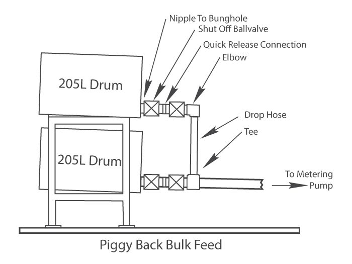
If the material is flowable it may be able to be fed from bulk (205L or 20/25L) drum. Ideally the pump should be lower than the drum to give head, but once primed the pump will generate suction. However at best this will only be 1Bar differential pressure and this may limit the feed rate. Changing the empty drums can be a problem, invariable it empties at the wrong time so the machine has to be stopped. Moreover air can be introduced and the pump may need bleeding. This can be overcome by using two drums with one drum above the other and tee’d together. With the additional head the top drum will empty first but leave the bottom drum full to give continuity of feed and time to change the top empty one.

Lota Range

However if the material is not flowable enough to feed from the drum it will transferred by a secondary pump. These are normally proprietary pneumatically powered and range from;

Diaphragm pump for low viscosity materials. These can be coupled to the drum with a hose or fitted with a dip tube which immerses into the drum. They have a 1:1 intensification ratio so will not generate much pump power. However as there are no wetted dynamic seals that may leak, they are ideal for pumping hygroscopic materials and can be made from plastic.

Ball type pump for low to medium viscosity materials. These can range from 1:1 up to 50+:1 intensification ratio, so are capable of transferring long distances and you can buy lower intensification pumps which can be immersed into the drum through the bung hole.

Extrusion pump for high viscosity, non flowable material, these normally range from 20 up to 60:1ratio and comprise a pump mounted into the middle of a follower plate with a wiper blade sized to the inside diameter of the drum. The assembly is fitted to a pneumatic lift or lift/ram so the drum can be slid underneath the follower and then lowered down inside the drum to rest on top of the material. The pump has to be bled of air but once primed and pumping the differential pressure will push the follower plate down.

However it takes times to change drums over, the machine has to be stopped and this may be a problem on a production line. To overcome the problem the extrusion pump can be used to feed to an accumulator close to the metering pump to act as a buffer and allow the time to change drums over. \these also act as a pressure reducer as metering pumps do not the high inlet pressure generated by the extrusion pump.

The alternative to a transfer pump is to meter directly from the drum, with either a piston or gear metering pump in the follower in place of the extrusion pump. On paper it looks the obvious method of handling thick materials in 205 or 25L drums, but in practise it can be fraught with problems. The most common being a dented drum which stops or let’s air in to the follower and throws the machine off mixing ratio.

However, most machines are fed from reservoirs. Once the material is inside it’s reservoir it should have the same shelf life as inside the supplied container. Therefore it is best to size the reservoir to be a minimum1.5 x the container size. Thus when the reservoir is empty it will accept a full container to be decanted in to it, then close the lid and the risk of contamination will be minimised. If you are using say 50L. of material per day and buying it in 20L drums make the material 70L capacity. Many materials are hygroscopic, sensitive to airborne moisture; the reservoir can be sealed and vented through a silica gel trap or fed with oxygen free (dry nitrogen). Therefore, so a rule the less the tank lid is off the better.

The 1 Bar suction from the pump applies to reservoirs and as they are normally coupled directly, or close to the pump simple gravity fed type will suffice. If not then overpressure is required say 2 or 5 Bar. Technically not an issue, but due to legislation making a one off bespoke tank is now very expensive, be prepared to compromise to if possible use a standard type pressure vessel.

The reservoirs are used for preparation of the material as this can be more easily done on a batch basis rather trying to do it online through the metering pumps a mixer. Normally what is fed into the metering pumps will come out through the mixer without entraining any air. So, if the material is poured in ‘air free’ it will come out air free. With many applications this is sufficient, but if there is air in the material this can affect the metering and/or the final product. Therefore the material has to be de-gassed in the reservoirs prior to metering. When the material is being degassed the entrained air in the material will expand and the material will rise in the reservoir, although the expansion is not as violent as degassing a hand mixed sample so allow for 1.5 to 2 x volume rise in the reservoir. With degassing, the larger surface area in contact with the applied vacuum the better. Thus a large diameter shallow is preferable to a small diameter deep reservoir. Stirring where fresh material is brought up to the surface in contact with the vacuum will speed up the process. Similarly ‘Thin Filming’ where the material is drawn up from the bottom of the reservoir then spread as a thin film over a plate will speed up degassing . Although as a stating point it is better to opt for a large diameter, shallow design.

Material may need to be heated for a number of reasons, they can be solid or waxy at room temperature, need to be mixed hot, too thick at ambient to flow easily or need to reduce the variability of the material by keeping the temperature up above ambient. As a general rule for epoxies and polyurethanes (PU) a 10Deg. C change in temperature will factor the viscosity times 2. So, clearly warming up a thick material will make it easier load and pump through the machine. However this times 2 figure also applies to the mixed gel time; this may sound like a worry, but often the mixed material is applied to or poured into a good heatsink that will cool it down. As such most materials are poor conductors; it takes time to heat up or cool down. Therefore heating is best done in the reservoirs where there is time to apply the heat, and if the rest of the machine has to be heated work on the basis that this will be holding, rather than elevating the temperature.

Heating the machine can be done by

Environmental; where the machine is enclosed in an insulated hot box warmed by infra red lamps or fan heater. This is simple, very effective as it warms the whole machine and can be used to pre-warmed material prior to decanting into the machine. There are limitations such as access to the machine. Although it can be done at low cost it seems to often overlooked.

Electrical; using trace wire for hoses or silicone rubber mats or cartridge heaters for the reservoirs and metering pumps. This is the most commonly used method. The heating can be targeted effectively although each zone needs to be controlled separately. Also there are limits to how much heat can be transferred without creating localised hot spots which may degrade the material.

Liquid; where the reservoirs and component hoses are fitted with outer jackets. Hot liquid (water up to 85deg.C or oil up to 150Deg.C) is then pump through them using a recirculatory heater unit. It is generally accepted liquid is the best heating method as it offers a uniform temperature over a large area. However it can be expensive if just heating one part/zone of the machine.

When heating reservoirs you may also have to consider stirring. This will help to speed up the heating process as it will bring fresh material in to contact with the heating surfaces. Also with filled material it will help to keep the filler in suspension.

There are numerous designs and types of metering pumps, but the metering pump is just part of the machine. When connected to the mixer by hoses then a hysteresis effect is introduced. Hoses are elastic; they expand as pumping pressure builds up and then retract as the pressure decays. The pumps may start pump material together on ratio as the enter they hose, but if the hose expansion caused by the pumping pressure are different, then they will not come out together as they leave their hoses and into the mixer. This will give a momentary ‘off Ratio’ period which can be seen in the final product. This can be minimised by sizing the hoses to balance the pressure expansion or by altering the pumping so as one starts before the other, but in practise this is not always possible, moreover the pressure may vary with temperature or batch.

Thus a metering problem can be due to presentation caused from the hoses rather than the metering pumps.

Therefore if viable it is better to move the part to a mixer fitted onto the machine than move a mixer fed with flexible hoses to the part.

Metering pumps comprise two forms of motion, rotary (gear type) or reciprocating (piston type) and dependant for a given application each style offers advantages or disadvantages.

Lobe and centrifugal piston pumps are rotary action and work as metering pumps, but predominately gear type pumps are used. Either as ‘High Pressure’ type commonly used high outputs for fast reacting foam systems and impingement mixing and ‘Low Pressure’ and these are mainly external type (see gear pump image) where two meshing spur gear pumps are retained in a close fitting ‘race track’ housing and held between two side plates. Material is fed in the housing and carried around the outside between the teeth of the gear wheel and as the gear wheel mesh it is squeezed/pumped out. Thus the metering is effectively continuous with minimal pulsation and pressure fluctuation. They can be bought in a number of sizes with the displacement per revolution being a function of the number of teeth, module and face width.

Lota Range

Although for the gears to rotate there has to be a running clearance around the gear tips and race track also between the gear faces and slide plates. However where there is a clearance and where there is a gap slippage can take place. The level of slippage depends on numerous factors, gap, viscosity, surface speed and pressure differential. It may not be detectable but it is inherent in the pump design. Thus there is always a question over running filled/abrasive materials as the wear in the pump increases the running gaps. In practise this may not always be as bad as it sounds; although with the faces rubbing together it limits the choice in construction materials for the pump and also the pump speed which effects slippage. It is easy to state that with pumps you get what you pay for, but by and large the pumps are not designed for metering resins and hardeners. Some pump manufactures offer metering pumps with replaceable figure 8 wear/rubbing plates which fits between the gear sides and housing. These can be used a few times although eventually the gear teeth and race track housing wears, slippage can take place and this is not always noticeable until there is back pressure in the line. In practise gear pumps have an optimum speed range, too fast the wear out, too slow and they slip badly. Most machine manufacturers advertise staring they use ‘precision’ pumps, but there is ‘precision’ and there is ‘precision’ to this end a good quality precision pumps will meter say 10mPas at 10 to 150 Revs/ Minute. However a good quality pump would not meter 150mPas below 90 Revs/ Minute but would then run up to over 500 Revs/ Minute.

Being rotary motion, gear pumps are simpler and easier to drive by using an inverter or servo controlled motors and then interlock the motor drives electronically. As well as the metering pump speed ranges the drives also have limits on their speed range therefore it is important to match the motor drive speed to the pump speed range Most gear pump machine use inverter drives. Although these offer a wide speed range, in practise where you want the motor speed to be proportional to the signal the range is limited to 5 ~ 6:1 ranges, E.g. 20 to 130 Revs/minute. It is fairly simple to close loop the drive motors to maintain their speed ratio. However, this does not mean it is also maintaining the pump metering ratio, if a pump is worn and slipping the mixing ratio will drift.

Gear Pump Drives

This can be overcome by secondary flow metering mounted in the line between the metering pump and mixing head. Typically this is done using a precision external gear flow meter or where the material is abrasive a Mass Flow meter. However both types require time to stabilise when starting from a no flow condition. Therefore if hysteresis is a problem it may be better to fit them into a recirculation loop from the metering pump up to changeover valves to switch to the return line back to reservoir or through the mixing head mixing head.

An alternative to using electronically interlocked individual motor pump drives is to use a single motor and mechanically interlock the pumps using toothed pulleys and a timing belt, with the mixing ratio set by a combination of pump displacements and pulley teeth. This method is simple, effective and eliminates operator involvement. However a timing belt means the pumps have to be close together, thus in overall machine terms a single motor drive may not necessarily be the cheapest drive method.

There are two commonly used reciprocating piston pumps, Single or Double acting.

Single acting:

This pumps in one direction, and then reloads as it returns. Typically a single acting pump comprised a flexible skirt seal, which either has a rod pushed through it, or the seal is pushed down a tube; displacing the material in front of it and through a non return valve. As pump reverses the valve closes and pulls a vacuum and this is broken as the rod leaves the seal, or the seal leaves the tube. This leaves a differential pressure (suction) which assists the pump reloading ready for the next cycle. Effectively seal as an inlet non return valve, but a large port and with the suction has a high viscosity acceptance.

Single acting

The pump is conceptually simple; it will accept high viscosity materials without the need for additional feeding pressure. The flexible skirt is self energised by the pumping pressure and can self compensate for wear... Therefore by controlling the pumping stroke it can accurately meter a discrete shot. However, tin one direction he flexible skirt generates a wedging action trapping fillers which may be a problem. Also in some cases as the pump drives forward towards the point it starts to meter it can generate a high pressure pulse in front of it and the can open a conventional sprung loaded non return valve on the outlet., giving a momentary material witness. Moreover being single acting the flow is interrupted, when fitted with hoses the high/low pumping pressures give pronounced pulsation. This may not be as bad as it seems but when feeding to an online mixer it can causes problems in the mix.

Double acting:

This pumps in both directions. Typically comprise a flexible skirt pistons retained in a tube with ports at each end fitted with directional 3 way (inlet-outlet) valves. As material is being metered through the outlet one end it is being fed with fresh through the inlet the other end. When the pump reaches the end of its stroke the valves change over and the piston reverses to meter in the opposite direction. Thus although there is still some pulsation it give a semi continuous flow.

Being reciprocating motion, piston pumps are easily driven by pneumatic (air) or hydraulic cylinders and air cylinders are cheap and generally reliable. Unlike electrical drives, air cylinders can be stalled, an advantage often put to use in machine control. However air is more difficult to control for pump flow rate, moreover the backpressure on pumping is often variable This controlling rate problem is more acute with single acting pumps where part of the pumping stroke is pre-travel prior to metering.

Where an accurate flow rate is required it is better to use non compressible oil rather than air. Or better still, use a recirculatory ball screw and either a programmable servo or stepper drive although with its’ low speed torque characteristics the cheaper stepper drive is often best suited.

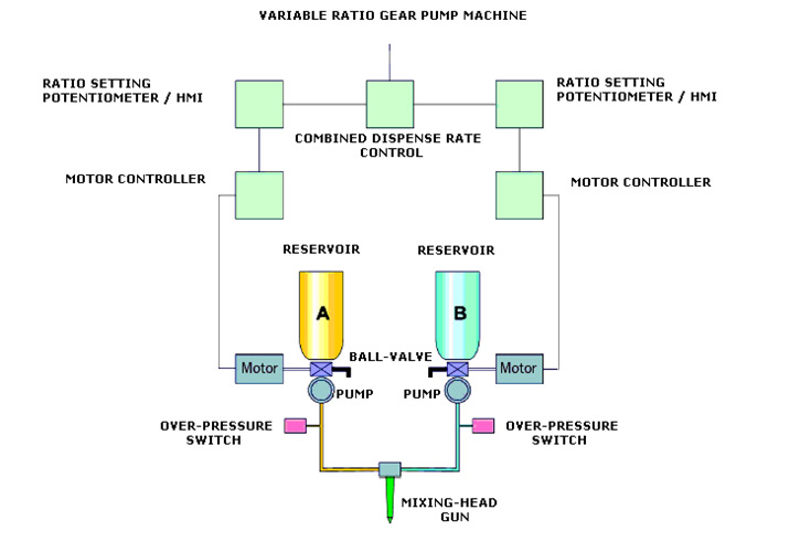
Because of the control problem associated with air drives you can not drive these pumps individually. Therefore the metering pumps have to be mechanically locked together to ensure they start, travel, at the same rate and stop together.

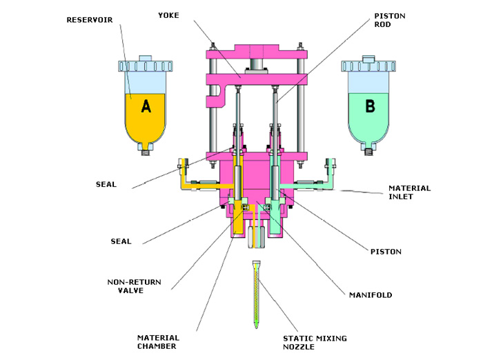
This can be done with a simple bar (yoke) linking the drive and metering pumps together, with their diameters sized to the required ratio. Thus the machine is a ‘Fixed’ or ‘Pre-set’ ratio’ (see sketch)

Alternatively a hinged or scissor action linkage can be used which will allow a degree of adjustment on the relative pump stroke, whilst still starting and stopping together this machine being ‘variable ratio’

The question whether the piston pump machine should be ‘fixed’ or ‘variable’ ratio is often raised.

With few exceptions, such as Polyesters, Hybrids or Pre-polymer PU, most two component materials are formulated to mix at a fixed ratio and at fairly close tolerance, if they are mixed ‘Off Ratio@ then the physical properties may be impaired, eventually to a point it will not react and cure together. Therefore with most materials the only time the machine has to change its’ ratio is when the material being changed. If the ratio drifts or moves in use, there is something wrong with the machine. Adjusting the ratio may be a temporary fix, but it will not necessarily cure the problem with the machine. When changing material and thus ratio, adjusting the ratio is the easiest part. The hardest part is cleaning the machine to avoid cross contamination and invariable this means dismantling the metering pumps. At this stage it normally advisable to replace the parts anyway, so the advantage of a variable ratio machine is perceived rather than actual.

The general advantages of a gear over a piston pump are:

As they may only need to start and stop once, they provide steady, near pulsation free continuous flow characteristics for online mixing, thus generally providing better, more homogenous mixing. They are capable of higher outputs. The rotary is easier to control then reciprocating motion, thus changing flow rates or mixing ratio can be simpler. The ability to electronically interlink individual pump drives offers greater flexibility in machine layouts. There is less to go wrong gear pumps are simpler in design and a rotary running in one direction is inherently superior to a reciprocating seal.

The general advantages of a piston over a gear pump. From thick to thin the readily accept a wider range of material viscosities. Less likely to suffer from slippage especially where back pressure is changing They offer greater flexibility in construction materials, therefore easier to assure chemical compatibility or overcome abrasion problems. They are normally pneumatically powered and therefore easier to use in hazardous areas. They are easier to integrate to with mixer as a single unit, eliminating hose hysteresis. Generally piston are cheaper than gear pump machines.

From the above it should be clear that giving an application, one type of pump will be better, or worse than the other. Although, as a general guide.

Where an application requires high or continuous output and large volumes, generally the gear is better than a piston type pump.

However if the amount required can be dispensed in a single piston pump cycle, the gear pump offers no advantage and if the amount is small then a piston is better than a gear pump.

Lobe and centrifugal piston pumps are rotary action and work as metering pumps, but predominately gear type pumps are used. Either as ‘High Pressure’ type commonly used high outputs for fast reacting foam systems and impingement mixing and ‘Low Pressure’ and these are mainly external type (see gear pump image) where two meshing spur gear pumps are retained in a close fitting ‘race track’ housing and held between two side plates. Material is fed in the housing and carried around the outside between the teeth of the gear wheel and as the gear wheel mesh it is squeezed/pumped out. Thus the metering is effectively continuous with minimal pulsation and pressure fluctuation. They can be bought in a number of sizes with the displacement per revolution being a function of the number of teeth, module and face width.

Although for the gears to rotate there has to be a running clearance around the gear tips and race track also between the gear faces and slide plates. However where there is a clearance and where there is a gap slippage can take place. The level of slippage depends on numerous factors, gap, viscosity, surface speed and pressure differential. It may not be detectable but it is inherent in the pump design. Thus there is always a question over running filled/abrasive materials as the wear in the pump increases the running gaps. In practise this may not always be as bad as it sounds; although with the faces rubbing together it limits the choice in construction materials for the pump and also the pump speed which effects slippage. It is easy to state that with pumps you get what you pay for, but by and large the pumps are not designed for metering resins and hardeners. Some pump manufactures offer metering pumps with replaceable figure 8 wear/rubbing plates which fits between the gear sides and housing. These can be used a few times although eventually the gear teeth and race track housing wears, slippage can take place and this is not always noticeable until there is back pressure in the line. In practise gear pumps have an optimum speed range, too fast the wear out, too slow and they slip badly. Most machine manufacturers advertise staring they use ‘precision’ pumps, but there is ‘precision’ and there is ‘precision’ to this end a good quality precision pumps will meter say 10mPas at 10 to 150 Revs/ Minute. However a good quality pump would not meter 150mPas below 90 Revs/ Minute but would then run up to over 500 Revs/ Minute.

There are various methods used for mixing materials together, but whatever is used, it must mix the components sufficiently well to meet the final requirements, but sometimes this can be overlooked.

The machines mix online and this often leads to confusion between bad mixing and bad metering/presentation of the individual components as the enter the mixer. If one component enters the mixer before the other component the machine is mixing off ratio until the come together.

If the end product is uniformly poor then it is either bad mixing (insufficient) or metering. However if the end product is good in parts , but bad in others, then invariably there is nothing wrong with the mixer, it is bad mixing or more likely bad presentation into the mixer.

There are four commonly online mixers used, Static, Rotary Static, Rotary /Shear or Dynamic and lastly impingement.

Static Mixers:
Static Mixers

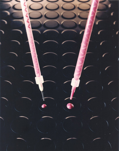
Also known as inversion mixing, although they can be constructed from stainless steel or aluminium, the most commonly used are the disposable plastic types. These can eliminate the need for solvent cleaning also when the material is cured they may be able to be treated as solid waste. Moreover, as they are extensively used with the convenience side/side duplex packaging they are a known quantity.

The original disposable static mixer was based on the old Kenics mixer element patent and with a simple 17 I/Dia bell end inlet with a nut for retention subsequently although there has been numerous other designs, generally they comprise a series of mixing elements retained in a tube. As the stream of metered components pass through the tube, each element splits and segregates the stream into multiple streams, which in turn are split again as they pass through the next stream and so on a linear fashion. Therefore with say a mixer where the element design splits in two, then the next will split in 4, then 8, 16, 32 and so on, therefore the more elements, the more segregations and hopefully the better the mix. However as mentioned above if one component enters in front of the other it will just mix itself until the other stream enters. Also, although these splits may run into the millions but it does not necessarily mean the components are mixed well together. This because there is no shear action and some materials (notable high grade and foam Polyurethanes), like the shear action where they need to be knocked together, rather than lay side by side with by static mixing.

Rotary/Static Mixer

The next stage up is combining the disposable static with some shear action. This is done by connecting a motor to a loose fitting element stack which can then rotated inside the tube. This imparts a degree of shear action between the outside of the stack and the inside wall of the tube. Being disposable it again eliminates the need for solvents. However being plastic, the shear action is limited by the torque that can be transmitted through the element stack and stack element tip surface speed. Moreover, although they may be termed disposable, they are not necessarily solvent free as the connection to the motor has to be cleaned.

Rotary/Dynamic Mixers:

Where a higher level of shear energy is required to mix the components, a rotary or dynamic mixer needs to be used. This comprises a spinning rotor in a fixed mixing chamber as the components pass through the chamber they are sheared together between the inside of the chamber and rotor. The faster the rotor tip speed and the closer the gap between them, higher the shear action. There are various designs of mixing chamber and rotor, but generally split into two groups, Peg or Tooth and Screw type rotor. The peg type having rows of teeth on the rotor, these meshing with teeth on the inside wall of the chamber, giving a large shearing area. Whereas the Screw type has a smooth inside chamber and uses a close fitting rotor with a series of helical grooves on the outside. These stretch the material, pulling the components together to help mixing.

Choosing the design and size to give the best results for a specific application may require tests. However in practise the Peg type mixers are generally used for mixing solid materials such as epoxies or PU elastomers and the Screw type for foam systems. Due to the shearing action both types of mixer generate heat and thus a temperature rise in the mixed material. Therefore with fast curing systems a balance between mixer residual volume, the material gel time and the throughput has to be considered, although fast gelling ( 2~3 seconds) PU elastomers have been mixing for years, so it is just getting the balance.

However, the wetted parts (inside of mixing chamber and rotor) will need cleaning before the mixed material is cured. During production time this can be achieved by purging/pushing the mixed components out the chamber before they start to gel with fresh material. Often this is done automatically with a presetable timer ( commonly known as an Anti-Gel Timer or AGT) this switches on every time the pumps start, counts down then signals the pumps to put a shot through the mixer. Having done so, it resets itself to count down for the next shot and so on and with fast curing materials The AGT can be linked to a counter to limit the purging shots as sometimes it is cheaper to throw the mixer away than the material. Also this does not necessarily fully clean the mixer and the can be a steady build up of curing the material inside which can effect the mix quality.

Therefore the wetted parts have to be washed and cleaned. Sometimes the removal of reacting material can be achieved by purging through with a single component to leave the mixer full of non reactive material, but invariable there will be a trace of reacted material left. Moreover this then has to be purged out with mixed material before the machine can be used. The alternative is to clean out with a flushing media and then dry this out with air. As to the flushing media this could be warm soapy water or a citrus cleaner, but probably it will be a solvent and this can be a problem, both in use and disposal. The choice of solvent will depend on the material to be processed, some work better with epoxies than PU and vice versa. Although as a general rule the good solvents for cleaning are nasty to use and the solvents that are good to use are nasty for cleaning. If you have any doubts over this talk to your material supplier for advice. Moreover it is not too difficult to flush straight into a bucket inside a tank fitted with extraction.

As mentioned the machine can be fitted with an AGT to purge old mixed material with fresh. Most material technical data sheet (TDS) give a Work or Pot Life time figure which is normally based for a 100gm mass at 23 Deg.C , so the AGT can be set for a time period for this to either give an audible warning or a dispense a shot of fresh material to purge out the old curing material. In practise because heat generated by the shear action in a rotary mixer it is better to make the time shorter, whereas with disposable static mixer the small residual mass can slow the reaction and it may be possible to extend this time.

Here the metered component streams under pressure are ported so as they are brought to blend together. This can be done so the mix externally or inside a small chamber fitted with a plunger. At rest the plunger closes the component ports, when it is withdrawn the ports are opened allowing the components to come together and start mixing. Then as the plunger is pushed forward it closes the ports and the pushes any residual material out of the chamber.

Although it is very simple, depending on the material and viscosities it may need very high pressures to mix and this also limits low output rates. Therefore of the four types of mixing impingement is perhaps the most specialised and least widely used.

Whichever type of mixer is used, the priority is it has to mix sufficiently to meet any performance demands placed on the finished mixed product.

With eliminating the use of cleaning solvents and assuming it will mix the material, then the disposable static mixer should be the most attractive method mixing types. They are the least cost also if it has to be hand held, then the lightest and least cumbersome. However the element stack fitted inside the tube can create a high pressure drop, which being plastic construction can limit the output rate. Also as they segregate linearly there is a danger that any interruptions in the metering flow can result with an ‘Off Ratio’ patch in the mix.

However if the material can not be mixed with a static , then in many cases it is better to go directly to the dynamic mixer, rather than the rotary static type. Whilst on paper the rotary static may look attractive, there are limitations on what the can do as to mixing and output and they still need solvent for cleaning. If shear action is required for mixing then it is better to use a rotary dynamic mixer.

What is safe to assume is, when processing say a standard polyurethane elastomers through a metering and mixing machine. Then the mixed physical performance will be better with a rotary dynamic than a rotary static and in turn this will be better that with a static mixing. This does not mean that the static mixing may not be good enough, only that the dynamic will be better.

Therefore as a general guidance to what can/cannot be mixed with a disposable static on commonly used materials…

Although the adhesives mix easily through disposable static mixers, with the 1:1 ratio systems often 5~7 mixing elements may suffice and their reaction can be quite quick, therefore the residual volume in the mixer needs to be considered. Also, if you are upgrading to a mixing machine from side/side syringes using a disposable mixer with bayonet (twist and lock) type fastening, they may cause a problem due to cross contamination on the machine outlet. The syringe being disposable if the outlet blocks up whereas the machine is not. You can still use the mixer but this has to be pushed on the outlet and held on with a nut.

Adhesives, casting or matrix resins and encapsulants should all mix with a static. Although if the metering machine is feeding a high ratio, thick/thin and high low density encapsulants to the mixer with hoses may be a problem. Although it may mix the hose presentation may give off ratio patches.

These generally need shear action for mixing, so are more difficult the static mix and the more refined the isocyanate and the higher their performance the greater the need for dynamic mixing.

They do not mix well through a static, they really need shear or impingement mixing to provide a good cell structure.

The very high viscosity adhesives may cause problems due to the pressure drop through the mixer; otherwise normally this should be straightforward.

TWith the above rider over high ratio, thick -thin systems rider; Polyol – crude MDI isocyanates are normally straightforward, whereas some PolyBD and refined MDI systems need careful attention but should static mix

Castings, mouldings and coatings. As a general rule if they do static mix it should be treated as a bonus; although many of the simple polyether polyol/ MDI systems will static mix satisfactorily. However, the higher performance polyester polyol materials may not, similarly a hard PU is more likely to static mix than a soft PU.

Therefore with PU elastomers it is best to assume they will not static mix.

Used as a matrix resin such as in GRP static mixing is OK. However used as a casting resin then dynamic mixing generally gives homogeneous mix.

Most commonly used adhesives and encapsulants will static mix.

Most moulding rubbers will disposable static mix down to say 5% catalyst (100:5 mix ratio) although what is often a limiting factor with viscous base rubber is the output rate.

In automating the process, engineers strive for stability. However, most two component materials are anything but stable. There are various reasons for this, but primarily it is due to temperature changing viscosity. This affects the material flowability and pressure drops which changes the response time to a signal.

The simple way to reduce this variability problem is to elevate the material temperature to above ambient, say 35 ~ 40 Deg. C. Materials tend to be poor heat conductors, so it may take time to heat up, therefore it is advisable to heat the reservoirs to get the material up to the required temperature, then heat the pumps and any hoses to maintain the temperature. This may reduce the variability, but if the mixing head is being fed with flexible hoses a response delay between signalling the pumps and witnessing flow from the mixer is inherent. My personal record response delay time was 5 seconds on a robotically applied direct glazing sealant. In itself, 5 seconds was not a problem as the robot could be programmed to delay it’s travel, but if the 5 became 4.5 or 5.5 seconds it is a major problem and there are two standard ways to overcome this.

Firstly, avoid using hoses by integrating the metering pumps with the mixer into a single unit on the end of the robot.

Secondly, to run recirculation hose loops from the pumps up to the mixing/dispensing head fitted with valves to divert the flow either through the mixing head or down a hose returning the material back to the reservoir. This return hose being fitted with a fluid pressure regulator to balance dispense and return pressures.

Although both of these methods will overcome the response problem as neither are lightweight and this may and has been a problem with robot applications. Often the robot takes priority and it is quite common for a robot to be ordered before considering the requirements for the metering and mixing machine it has to use.

The point to remember is it does not matter how much you spend on the automating the metering and mixing machine, if the machine mixes rubbish, then that is what it is doing.

We hope the above will have given an insight in what is involved in specifying a metering and mixing machine; with the advantages/disadvantages of the individual building blocks for specific applications or requirements. We have tried to be impartial, also we do not know all there is to know about metering and mixing machines. It is not high technology, but it is still relatively new technology and as such we are still learning.